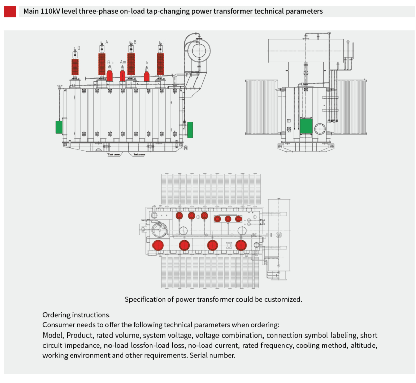

220kV THREE-PHASE ON-LOAD VOLTAGE REGULATING
TRANSFORMER
Summary
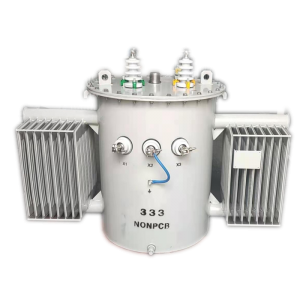
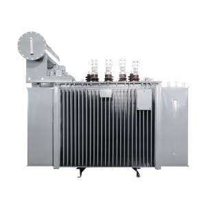
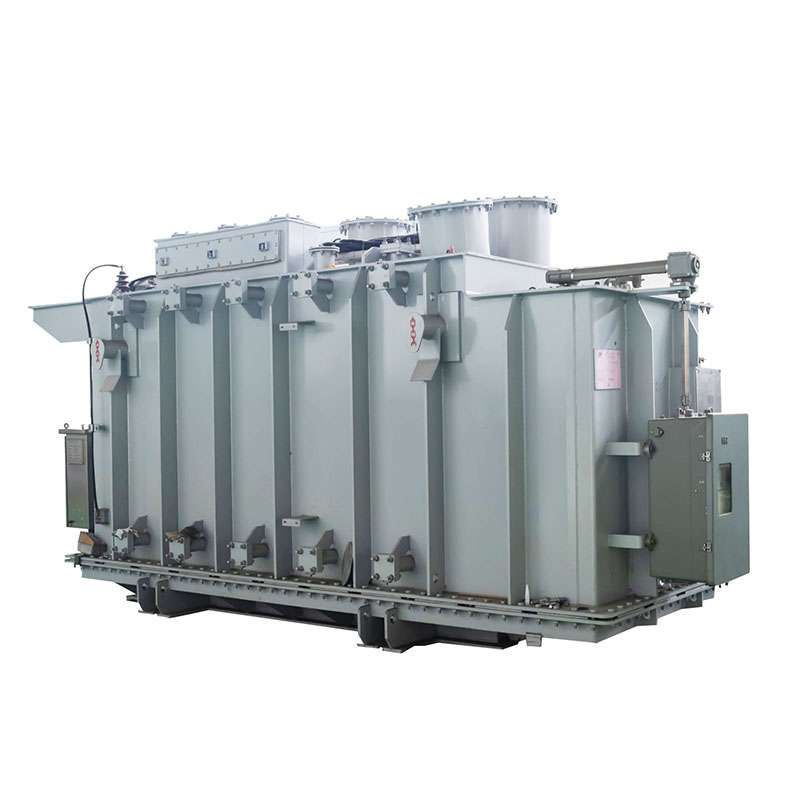
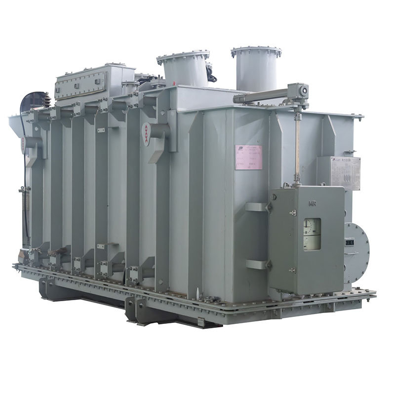
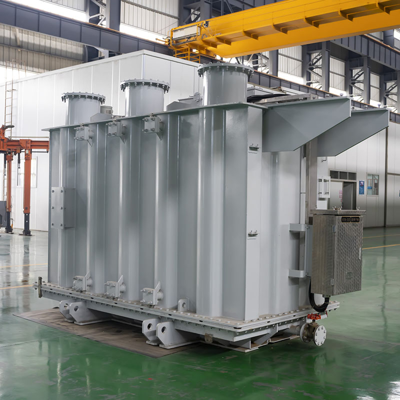
220kV three-phase oil immersed on-load voltage regulating transformer brings about a series of major transformations in terms of material, technique, and construction. It is characteristic of compact construction,
low weight, high efficiency, low loss, low noise, and reliability of performance. The product can reduce considerable losses on grid and operational costs and extend distinct economic efficacy.
The product meets following national standards: GB1094.1-2013 Power transformers Part 1: General; GB1094.2-2013
Power transformers Part 2: Temperature rise; GB1094.3-2003 Power transformers Part 3: Insulation levels, dielectric tests and external clearances in air; GB1094.5-2003 Power transformers Part 5: Ability to withstand short-circuit;
GB/T6451-2015 Specification and technical requirements for three phase oil immerse power transformers.
| Main 220kV level three-phase on-load voltage regulating power transformer technical parameters | ||||||||
| Rated Capacity (kVA) |
Voltage Combination | Vector Gourp | No-load Loss | Load Loss | No Load Current |
Short Circuit Impedance % |
||
| HV (kV) |
LV k(V) |
kW | kW | % | ||||
| 31500 | 6.3 6.6 10.5 11 |
YNd11 | 28 | 128 | 0.56 | 12-14 | ||
| 40000 | 32 | 149 | 0.56 | |||||
| 50000 | 39 | 179 | 0.52 | |||||
| 63000 | 46 | 209 | 0.52 | |||||
| 75000 | 10.5 13.8 |
53 | 237 | 0.48 | ||||
| 90000 | 64 | 273 | 0.44 | |||||
| 120000 | 75 | 338 | 0.44 | |||||
| 150000 | 220±2*2.5% | 10.5,11,13.8 | 89 | 400 | 0.40 | |||
| 160000 | 242±2*2.5% | 15.75 | 93 | 420 | 0.39 | |||
| 180000 | 18,20 | 102 | 459 | 0.36 | ||||
| 240000 | 128 | 538 | 0.33 | |||||
| 300000 | 13.8 15.75 18 21 |
154 | 641 | 0.30 | ||||
| 360000 | 17 | 735 | 0.30 | |||||
| 370000 | 176 | 750 | 0.30 | |||||
| 400000 | 187 | 795 | 0.28 | |||||
| 420000 | 193 | 824 | 0.28 | |||||
Note 1Transformers with rated capacity less than 31500 kVA and other voltage combinations can also be provided as required.
Note 2 Transformers with low voltage of 35 kV or 38.5 kV can also be provided as required.
Note 3 The non-splitting structure is preferred. If there is any requirement for operation, sub-connectors can be set up.
Note 4 When the average annual load rate of transformer is between 45% and 50%, the maximum operating efficiency can be obtained by using the loss value in the table.
| 31500-300000kVA three-phase three -winding non-field excitation changing power transformer | ||||||||||
| Rated Capacity (kVA) |
Voltage Combination | Vector Group | No-load loss kW |
Load loss kW |
No load current % |
Short-circuit impedance(%) | ||||
| High Voltage kV |
Med-ium Voltage (kV) |
Low Voltage (kV) |
Step down | Step down | ||||||
| 31500 | 6.3,6.6 10.5,21 36,37 38.5 |
32 | 153.00 | 0.56 | ||||||
| 40000 | 38 | 183.00 | 0.5 | |||||||
| 50000 | 44 | 216.00 | 0.44 | |||||||
| 63000 | 52 | 257.00 | 0.44 | H-M | H-M | |||||
| 90000 | 220±2*2.5% | 69 | 10.5,13.8 21,36,37 38.5 |
YNyn0d11 | 68 | 333.00 | 0.39 | 22-24 | 22-24 | |
| 120000 | 230±2*2.5% | 115 | 84 | 410 | 0.39 | H-L | H-L | |||
| 150000 | 242±2*2.5% | 121 | 100 | 487 | 0.33 | 12-14 | 12-14 | |||
| 180000 | 10.5,13.8 15.75,21 37,38.5 |
113 | 555 | 0.33 | M-L | M-L | ||||
| 240000 | 140 | 684 | 0.28 | 7-9 | 7-9 | |||||
| 300000 | 166 | 807 | 0.24 | |||||||
Note 1: The capacity allocation of load loss in the table is (100/100/100)%. The capacity allocation of boost structure can be
(100/50/100)%. The capacity allocation of Buck structure can be (100/50/100)% or(100/50/100)%.
Note 2: Transformers with rated capacity less than 31500 KA and other voltage combinations can also be provided as required.
Note 3: Transformers with low voltage of 35 kV can also be provided as required.
Note 4: Priority should be given to non-splitting structure. If the operation requires, splitting can be set.
Note 5: When the average annual load rate of transformer is between 45%, the maximum operating efficiency can be obtained by using the loss value in the table.
| 31500kVA-180000kVA three-phase duplex-winding on-load tap changing power transformer | |||||||||
| Rated Capacity (kVA) |
Voltage Combination | Vector Gourp | No-load Loss | Load Loss | No Load Current |
Short Circuit Impedance % |
|||
| HV (kV) |
LV k(V) |
kW | kW | % | |||||
| 31500 | 6.3,6.6 10.5,11,21 36,37 38.5 |
30 | 128 | 0.57 | 12-14 | ||||
| 40000 | 36 | 149 | 0.57 | ||||||
| 50000 | 43 | 179 | 0.53 | ||||||
| 63000 | 50 | 209 | 0.53 | ||||||
| 90000 | 64 | 273 | 0.45 | ||||||
| 120000 | 220±8*1.25% | 10.5,11,21 36,37 38.5 |
YNd11 | 79 | 338 | 0.45 | |||
| 150000 | 230±8*2.5% | 92 | 400 | 0.41 | |||||
| 180000 | 108 | 459 | 0.38 | ||||||
| 120000 | 81 | 337 | 0.45 | ||||||
| 150000 | 66 69 |
96 | 394 | 0.41 | |||||
| 180000 | 112 | 451 | 0.38 | ||||||
| 240000 | 140 | 560 | 0.30 | ||||||
| 31500kVA-240000kVA three-phase three-winding on-load tap changing power transformer | |||||||||
| Rated Capacity (kVA) |
Voltage Combination | No-load Loss | Load Loss | No Load Current |
Vector group | Short Circuit Impedance % |
Capacity Assignment |
||
| HV (kV) |
Med-ium Voltage (kV) |
LV k(V) |
kW | kW | % | ||||
| 31500 | 6.3 6.6 10.5 11 21 33 36 37 38.5 |
35 | 153.00 | 0.63 | H-M 12-14 H-L 22-24 M-L 7-9 |
100/100/100 100/50/100 100/100/50 |
|||
| 40000 | 41 | 183.00 | 0.60 | ||||||
| 50000 | 48 | 216.00 | 0.60 | ||||||
| 63000 | 69 | 56 | 257.00 | 0.55 | |||||
| 90000 | 220±8*1.25% | 115 | 10.5 11 21 33 36 37 38.5 |
73 | 333.00 | 0.44 | YNyn0d11 | ||
| 120000 | 230±8*1.25% | 121 | 92 | 410 | 0.44 | ||||
| 150000 | 108 | 487 | 0.39 | ||||||
| 180000 | 124 | 598 | 0.39 | ||||||
| 240000 | 154 | 741 | 0.35 | ||||||
Note 1The data listed in the table are applicable to depressurized structural products, and boost structural products can also be provided as required.
Note 2 Transformers with low voltage of 35 kV can also be provided as required.
Note 3 When the average annual load rate of transformer is between 45% and 50%, the maximum operating efficiency can be obtained by using the loss value in the table.
| 31500kVA-240000kVA three-phase three-winding on-load self-coupled power transformer | |||||||||
| Rated Capacity (kVA) |
Voltage Combination | No-load Loss | Load Loss | No Load Current |
Vector group | Short Circuit Impedance % |
Capacity Assignment |
||
| HV (kV) |
Med-ium Voltage (kV) |
LV (kV) |
kW | kW | % | ||||
| 31500 | 6.3 6.6 10.5 21 36 37 38.5 |
20.0 | 102 | 0.44 | YNyn0d11 | H-M 8-11 H-L 28-34 M-L 18-24 |
100/100/50 | ||
| 40000 | 24.0 | 125 | 0.44 | ||||||
| 50000 | 28.0 | 149 | 0.39 | ||||||
| 63000 | 33.0 | 179 | 0.39 | ||||||
| 90000 | 220±8*1.25% | 115 | 40.0 | 234 | 0.33 | ||||
| 120000 | 230±8*1.25% | 121 | 10.5 21 36 37 38.5 |
51.0 | 292 | 0.33 | |||
| 150000 | 60.0 | 346 | 0.28 | ||||||
| 180000 | 68.0 | 398 | 0.28 | ||||||
| 240000 | 83.0 | 513 | 0.24 | ||||||
Note 1 The data listed in the table are applicable to depressurized structural products, and boost structural products can also be provided as required.
Note 2Transformers with low voltage of 35 kV can also be provided as required.
Note 3 When the average annual load rate of transformer is between 45% and 50%, the maximum operating efficiency can be obtained by using the loss value in the table.
| 31500kVA-240000kVA three-phase three-winding on-load self-coupled power transformer | |||||||||
| Rated Capacity (kVA) |
Voltage Combination | No-load Loss | Load Loss | No Load Current |
Vector group | Short Circuit Impedance % |
Capacity Assignment |
||
| HV (kV) |
Med-ium Voltage (kV) |
LV (kV) |
kW | kW | % | ||||
| 31500 | 6.3 6.6 10.5 21 36 37 38.5 |
20.0 | 102 | 0.44 | YNyn0d11 | H-M 8-11 H-L 28-34 M-L 18-24 |
100/100/50 | ||
| 40000 | 24.0 | 125 | 0.44 | ||||||
| 50000 | 28.0 | 149 | 0.39 | ||||||
| 63000 | 33.0 | 179 | 0.39 | ||||||
| 90000 | 220±8*1.25% | 115 | 40.0 | 234 | 0.33 | ||||
| 120000 | 230±8*1.25% | 121 | 10.5 21 36 37 38.5 |
51.0 | 292 | 0.33 | |||
| 150000 | 60.0 | 346 | 0.28 | ||||||
| 180000 | 68.0 | 398 | 0.28 | ||||||
| 240000 | 83.0 | 513 | 0.24 | ||||||
1.Products exclusive in the product list may also be provided upon user requirements.Performance of the products will be customized.
2.Medium voltage device could select voltage value or tap other than those specified in the table upon user requirement.High voltage tapping may choose asymmetrical regulating tapping.
3.Short circuit impedance may choose value other than those defined in the table.
4.Final size is based on drawings of signed contract.