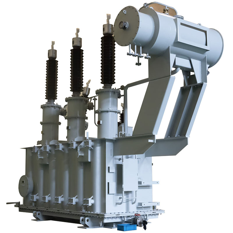
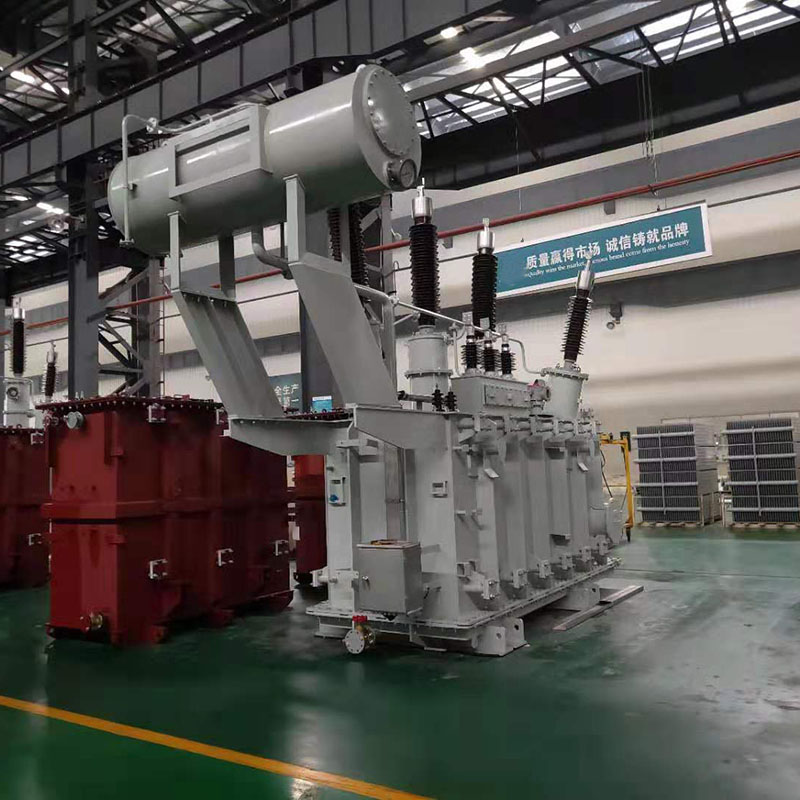
110kV LEVEL THREE-PHASE ON-LOAD TAP-CHANGING
ELECTRIC POWER TRANSFORMER
Summary
We have adopted series of important reforms on the 110kV level three-phase oil-immersed on-load tap-changing transformer referring material,
process and structure. The transformer has the features of small size, light weight, high efficiency, low loss, low noise, reliable operation etc,
which can reduce a large amount of power network loss and operation expenses with significant economic beneffts. It is suitable for power plant substation,
heavy section plant ore enterprises etc.
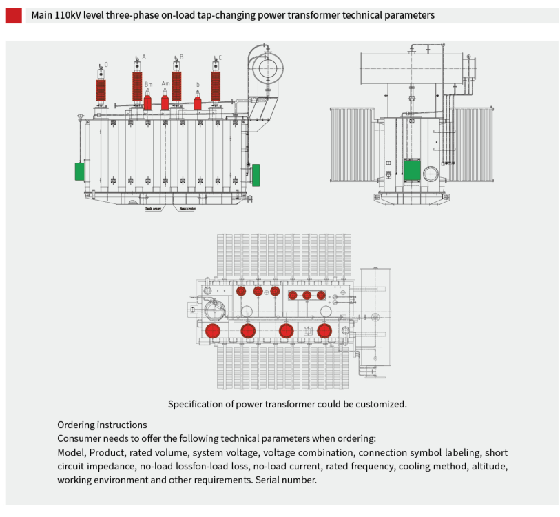
| Main 110kV level three-phase on-load tap-changing power transformer technical parameters | |||||||
| Rated Capacity (kVA) |
Voltage Combination | Vector Gourp | No-load Loss | Load Loss | No Load Current |
Short Circuit Impedance % |
|
| HV (kV) |
LV k(V) |
kW | kW | % | |||
| 6300 | 6.3 6.6 10.5 11 |
YNd11 | 7.40 | 35.0 | 0.62 | 10.5 | |
| 8000 | 8.90 | 42.0 | 0.62 | ||||
| 10000 | 10.50 | 50.0 | 0.58 | ||||
| 12500 | 12.40 | 59.0 | 0.58 | ||||
| 16000 | 15.00 | 73.0 | 0.54 | ||||
| 20000 | 17.60 | 88.0 | 0.54 | ||||
| 25000 | 110±2*2.5% | 20.80 | 104 | 0.50 | |||
| 31500 | 115±2*2.5% | 24.60 | 123 | 0.48 | |||
| 40000 | 121±2*2.5% | 29.40 | 148 | 0.45 | |||
| 50000 | 35.20 | 175 | 0.42 | ||||
| 63000 | 41.60 | 208 | 0.38 | ||||
| 75000 | 13.8 15.75 18 21 |
47.20 | 236 | 0.33 | 12-14 | ||
| 90000 | 54.40 | 272 | 0.30 | ||||
| 120000 | 67.80 | 337 | 0.27 | ||||
| 150000 | 80.10 | 399 | 0.24 | ||||
| 180000 | 90.00 | 457 | 0.20 | ||||
Note 1:-5% tapping position is maximum current tapping.
Note 2: For boost transformer, it is advisable to adopt non-tapping structure. If there is any requirement for operation, sub-connectors can be set up.
Note 3: When the average annual load rate of transformer is between 42% and 46%, the maximum operating efficiency can be obtained by using the loss value in the table.
| 6300kVA-63000kVA three-phase three -winding NLTC power transformer | ||||||||
| Rated Capacity (kVA) |
Voltage Combination | Vector Group | No-load loss kW |
Load loss kW |
No load current % |
|||
| High Voltage kV |
Med-ium Voltage (kV) |
Low Voltage (kV) |
Step down | |||||
| 6300 | 8.9 | 44.00 | 0.66 | |||||
| 8000 | 10.6 | 53.00 | 0.62 | |||||
| 10000 | 12.6 | 62.00 | 0.59 | |||||
| 12500 | 33 | 6.3 | 14.7 | 74.00 | 0.56 | H-M | ||
| 16000 | 110±2*2.5% | 35 | 6.6 | YNyn0d11 | 17.9 | 90.00 | 0.53 | 10.5 |
| 20000 | 115±2*2.5% | 37 | 10.5 | 21.1 | 106 | 0.53 | H-L | |
| 25000 | 121±2*2.5% | 38.5 | 11 | 24.6 | 126 | 0.48 | 18-19 | |
| 31500 | 29.4 | 149 | 0.48 | M-L | ||||
| 40000 | 34.8 | 179 | 0.44 | 6.5 | ||||
| 50000 | 41.6 | 213 | 0.44 | |||||
| 63000 | 49.2 | 256 | 0.40 | |||||
Note l: High, medium and low voltage winding capacity allocation is (100/100/100)% high, medium and low.
Note 2: The connection group label can be YNd11y10 as required.
Note 3: According to the user's requirement, medium voltage can be selected as different from the voltage value in the meter or with taps.
Note 4:-5% tapping position is maximum current tapping.
Note 5: For boost transformer, it is advisable to adopt non-tapping structure. If the operation requires, tapping can be set up.
Note 6: When the average annual load rate of transformer is about 45%, the maximum operating efficiency can be obtained by using the loss value in the table.
| Rated Capacity (kVA) |
Voltage Combination | Vector Gourp | No-load Loss | Load Loss | No Load Current |
Short Circuit Impedance % |
|
| HV (kV) |
LV k(V) |
kW | kW | % | |||
| 6300 | 8.00 | 35.0 | 0.64 | 10.5 | |||
| 8000 | 9.60 | 42.0 | 0.64 | ||||
| 10000 | 6.3 6.6 10.5 11 |
11.30 | 50.0 | 0.59 | |||
| 12500 | 6.6 | 13.40 | 59.0 | 0.59 | |||
| 16000 | 10.5 | 16.10 | 73.0 | 0.55 | |||
| 20000 | 110±8*1.25% | 11 | YNd11 | 19.20 | 88.0 | 0.55 | |
| 25000 | 21 | 22.70 | 104 | 0.51 | |||
| 31500 | 27.00 | 123 | 0.51 | ||||
| 40000 | 32.30 | 156 | 0.46 | 12-18 | |||
| 50000 | 38.20 | 194 | 0.46 | ||||
| 63000 | 45.40 | 232 | 0.42 | ||||
Note 1: On-load tap-changer, temporarily providing step-down structure products.
Note 2: According to user's requirements, other voltage combination products can be provided.
Note 3:-10% tapping position is maximum current tapping.
Note 4: When the average annual load rate of transformer is between 45% and 50%, the maximum operating efficiency can be obtained by using the loss value in the table.
| 6300-63000kVA three phase two winding OLTC power transformer | |||||||
| Rated Capacity (kVA) |
Voltage Combination | Vector Gourp | No-load Loss | Load Loss | No Load Current |
Short Circuit Impedance % |
|
| HV (kV) |
LV k(V) |
kW | kW | % | |||
| 6300 | 9.6 | 44.00 | |||||
| 8000 | 11.5 | 53.00 | |||||
| 10000 | 6.3 | 13.6 | 62.00 | ||||
| 12500 | 33 | 6.6 | 16.1 | 74.00 | H-M | ||
| 16000 | 36 | 10.5 | 19.3 | 90.00 | 10.5 | ||
| 20000 | 110±8*1.25% | 37 | 11 | YNyn0d11 | 22.8 | 106 | H-L |
| 25000 | 38.5 | 21 | 27.0 | 126 | 18-19 | ||
| 31500 | 32.1 | 149 | M-L | ||||
| 40000 | 38.5 | 179 | 6.5 | ||||
| 50000 | 45.5 | 213 | |||||
| 63000 | 54.1 | 256 | |||||
Note 1: On-load tap-changer, temporarily providing step-down structure products.
Note 2: High, medium and low voltage winding capacity allocation is (100/100/100)% high, medium and low.
Note 3: The connection group label can be YNd11y10 as required.
Note 4:-10% tapping position is maximum current tapping.
Note 5: According to user's requirement, medium voltage can be selected as diferent from the voltage value in the meter or with Note 5: When the average annual load rate of transformer is about 47%,the maximum operating efficiency can be obtained by using the loss value in the table.
| Rated Capacity (kVA) |
Voltage Combination | Vector Gourp | No-load Loss | Load Loss | No Load Current |
Short Circuit Impedance % |
|
| HV (kV) |
LV k(V) |
kW | kW | % | |||
| 6300 | 8.00 | 35.0 | 0.64 | 10.5 | |||
| 8000 | 9.60 | 42.0 | 0.64 | ||||
| 10000 | 11.30 | 50.0 | 0.59 | ||||
| 12500 | 6.3 6.6 10.5 11 |
13.40 | 59.0 | 0.59 | |||
| 16000 | 6.6 | 16.10 | 73.0 | 0.55 | |||
| 20000 | 110±8*1.25% | 10.5 | YNd11 | 19.20 | 88.0 | 0.55 | |
| 25000 | 11 | 22.70 | 104 | 0.51 | |||
| 31500 | 21 | 27.00 | 123 | 0.51 | |||
| 40000 | 32.30 | 156 | 0.46 | 12-18 | |||
| 50000 | 38.20 | 194 | 0.46 | ||||
| 63000 | 45.40 | 232 | 0.42 | ||||